
1) Preparation: This portion of the program selects the work and tool offsets, selects the cutting tool, turns on the coolant, sets spindle speed, and selects absolute or incremental positioning for axis motion.
2) Cutting: This portion of the program defines the tool path and feed rate for the cutting operation.
3) Completion: This portion of the program moves the spindle out of the way, turns off the spindle, turns off the coolant, and moves the table to a position from where the part can be unloaded and inspected.
This is a basic program that makes a 0.100" (2.54 mm) deep cut with Tool 1 in a piece of material along a straight line path from X = 0.0, Y = 0.0 to X = - 4.0, Y = - 4.0.
NOTE: A program block can contain more than one G-code, as long as those G-codes are from different groups. You cannot place two G-codes from the same group in a program block. Also note that only one M-code per block is allowed.
%
O40001 (Basic program) ;
(G54 X0 Y0 is top right corner of part) ;
(Z0 is on top of the part) ;
(T1 is a 1/2" end mill) ;
(BEGIN PREPARATION BLOCKS) ;
T1 M06 (Select tool 1) ;
G00 G90 G17 G40 G49 G54 (Safe startup) ;
X0 Y0 (Rapid to 1st position) ;
S1000 M03 (Spindle on CW) ;
G43 H01 Z0.1 (Tool offset 1 on) ;
M08 (Coolant on) ;
(BEGIN CUTTING BLOCKS) ;
G01 F20. Z-0.1 (Feed to cutting depth) ;
X-4. Y-4. (linear motion) ;
(BEGIN COMPLETION BLOCKS) ;
G00 Z0.1 M09 (Rapid retract, Coolant off) ;
G53 G49 Z0 M05 (Z home, Spindle off) ;
G53 Y0 (Y home) ;
M30 (End program) ;
%
These are the preparation code blocks in the sample program O40001:
This is referred to as a safe startup line. It is good machining practice to place this block of code after every tool change. G00 defines axis movement following it to be completed in Rapid Motion mode.
G90 defines axis movements that will be completed in absolute mode (refer to Absolute vs. Incremental Positioning (G90, G91) for more information).
G17 defines the cutting plane as the XY plane. G40 cancels Cutter Compensation. G49 cancels tool length compensation. G54 defines the coordinate system to be centered on the Work Offset stored in G54 on the Offset display.
M03 turns the spindle on in a clockwise direction. It takes the address code Snnnn, where nnnn is the desired spindle RPM.
On machines with a gearbox, the control automatically selects high gear or low gear, based on the commanded spindle speed. You can use an M41 or M42 to override this. Refer to page M41 Low Gear Override / M42 High Gear Override for more information on these M-codes.
On machines with a gearbox, the control automatically selects high gear or low gear, based on the commanded spindle speed. You can use an M41 or M42 to override this. Refer to M41 / M42 Low / High Gear Override for more information on these M-codes.
These are the cutting code blocks in the sample program O40001:
| Cutting Code Block | Description |
| G01 F20. Z-0.1 (Feed to cutting depth) ; | G01 F20. defines axis movements after it to be completed in a straight line. G01 requires the address code Fnnn.nnnn. The address code F20. specifies that the feed rate for the motion is 20" (508 mm) / min. Z-0.1 commands the Z Axis to Z = - 0.1. |
| X-4. Y-4. (linear motion) ; | X-4. Y-4. commands the X Axis to move to X = - 4.0 and commands the Y Axis to move to Y = - 4.0. |
| Completion Code Block | Description |
| G00 Z0.1 M09 (Rapid retract, Coolant off) ; | G00 commands the axis motion to be completed in rapid motion mode. Z0.1 Commands the Z Axis to Z = 0.1. M09 commands the coolant to turn off. |
| G53 G49 Z0 M05 (Z home, Spindle off) ; | G53 defines axis movements after it to be with respect to the machine coordinate system. G49 cancels tool length compensation. Z0 is a command to move to Z = 0.0. M05 turns the spindle off. |
| G53 Y0 (Y home) ; | G53 defines axis movements after it to be with respect to the machine coordinate system. Y0 is a command to move to Y = 0.0. |
| M30 (End program) ; | M30 ends the program and moves the cursor on the control to the top of the program. |
| % | Denotes the end of a program written in a text editor. |
Absolute (G90) and incremental positioning (G91) define how the control interprets axis motion commands.
When you command axis motion after a G90 code, the axes move to that position relative to the origin of the coordinate system currently in use.
When you command axis motion after a G91, the axes move to that position relative to the current position.
Absolute programming is useful in most situations. Incremental programming is more efficient for repetitive, equally spaced cuts.
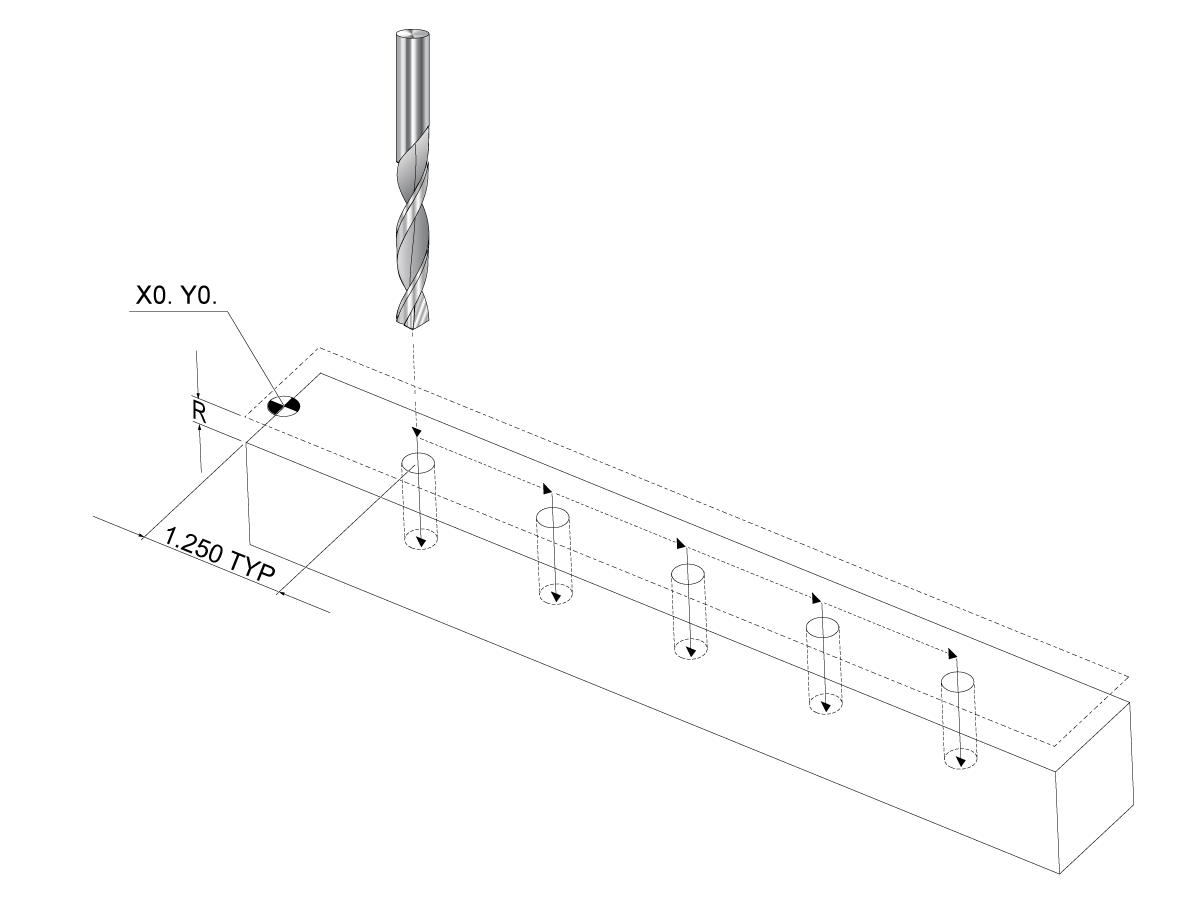
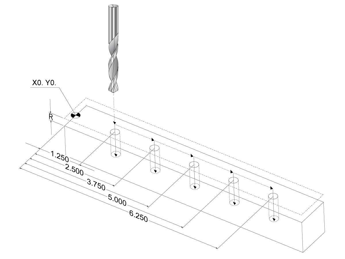
Figure Figure 1 shows a part with 5 equally spaced Ø0.25" (13 mm) diameter holes. The hole depth is 1.00" (25.4 mm) and the spacing is 1.250" (31.75 mm) apart.
Figure 1 shows a part with 5 equally spaced Ø0.25" (13 mm) diameter holes. The hole depth is 1.00" (25.4 mm) and the spacing is 1.250" (31.75 mm) apart.
Absolute / Incremental Sample Program. G54 X0. Y0. for Incremental [1], G54 for Absolute [2]
Below are two example programs that drill the holes as shown in the drawing, with a comparison between absolute and incremental positioning.
We start the holes with a center drill, and finish drilling the holes with a 0.250" (6.35 mm) drill bit. We use a 0.200" (5.08 mm) depth of cut for the center drill and 1.00" (25.4 mm) depth of cut for the 0.250" drill. G81, Drill Canned Cycle, is used to drill the holes.
%
O40002 (Incremental ex-prog) ;
N1 (G54 X0 Y0 is center left of part) ;
N2 (Z0 is on top of the part) ;
N3 (T1 is a center drill) ;
N4 (T2 is a drill) ;
N5 (T1 PREPARATION BLOCKS) ;
N6 T1 M06 (Select tool 1) ;
N7 G00 G90 G40 G49 G54 (Safe startup) ;
N8 X0 Y0 (Rapid to 1st position) ;
N9 S1000 M03 (Spindle on CW) ;
N10 G43 H01 Z0.1(Tool offset 1 on) ;
N11 M08(Coolant on) ;
N12 (T1 CUTTING BLOCKS) ;
N13 G99 G91 G81 F8.15 X1.25 Z-0.3 L5 ;
N14 (Begin G81, 5 times) ;
N15 G80 (Cancel G81) ;
N16 (T1 COMPLETION BLOCKS) ;
N17 G00 G90 G53 Z0. M09 (rapid retract, clnt off);
N18 M01 (Optional stop) ;
N19 (T2 PREPARATION BLOCKS) ;
N20 T2 M06 (Select tool 2) ;
N21 G00 G90 G40 G49 (Safe startup) ;
N22 G54 X0 Y0 (Rapid to 1st position) ;
N23 S1000 M03 (Spindle on CW) ;
N24 G43 H02 Z0.1(Tool offset 2 on) ;
N25 M08(Coolant on) ;
N26 (T2 CUTTING BLOCKS) ;
N27 G99 G91 G81 F21.4 X1.25 Z-1.1 L5 ;
N28 G80 (Cancel G81) ;
N29 (T2 COMPLETION BLOCKS) ;
N30 G00 Z0.1 M09 (Rapid retract, clnt off) ;
N31 G53 G90 G49 Z0 M05 (Z home, spindle off) ;
N32 G53 Y0 (Y home) ;
N33 M30 (End program) ;
%
The absolute program method needs more lines of code than the incremental program. The programs have similar preparation and completion sections.
Look at line N13 in the incremental programming example, where the center drill operation begins. G81 uses the loop address code, Lnn, to specify the number of times to repeat the cycle. The address code L5 repeats this process (5) times. Each time the canned cycle repeats, it moves the distance that the optional X and Y values specify. In this program, the incremental program moves 1.25" in X from the current position with each loop, and then does the drill cycle.
For each drill operation, the program specifies a drill depth 0.1" deeper than the actual depth, because motion starts from 0.1" above the part.
In absolute positioning, G81 specifies the drill depth, but it does not use the loop address code. Instead, the program gives the position of each hole on a separate line. Until G80 cancels the canned cycle, the control does the drill cycle at each position.
The absolute positioning program specifies the exact hole depth, because the depth starts at the part surface (Z=0).
%
O40003 (Absolute ex-prog) ;
N1 (G54 X0 Y0 is center left of part) ;
N2 (Z0 is on top of the part) ;
N3 (T1 is a center drill) ;
N4 (T2 is a drill) ;
N5 (T1 PREPARATION BLOCKS) ;
N6 T1 M06 (Select tool 1) ;
N7 G00 G90 G40 G49 G54 (Safe startup) ;
N8 X1.25 Y0 (Rapid to 1st position) ;
N9 S1000 M03 (Spindle on CW) ;
N10 G43 H01 Z0.1 (Tool offset 1 on) ;
N11 M08 (Coolant on) ;
N12 (T1 CUTTING BLOCKS) ;
N13 G99 G81 F8.15 X1.25 Z-0.2 ;
N14 (Begin G81, 1st hole) ;
N15 X2.5 (2nd hole) ;
N16 X3.75 (3rd hole) ;
N17 X5. (4th hole) ;
N18 X6.25 (5th hole) ;
N19 G80 (Cancel G81) ;
N20 (T1 COMPLETION BLOCK) ;
N21 G00 G90 G53 Z0. M09 (Rapid retract, clnt off);
N22 M01 (Optional Stop) ;
N23 (T2 PREPARATION BLOCKS) ;
N24 T2 M06 (Select tool 2) ;
N25 G00 G90 G40 G49 (Safe startup) ;
N26 G54 X1.25 Y0 (Rapid to 1st position) ;
N27 S1000 M03 (Spindle on CW) ;
N28 G43 H02 Z0.1 (Tool offset 2 on) ;
N29 M08 (Coolant on) ;
N30 (T2 CUTTING BLOCKS) ;
N31 G99 G81 F21.4 X1.25 Z-1. (1st hole) ;
N32 X2.5 (2nd hole) ;
N33 X3.75 (3rd hole) ;
N34 X5. (4th hole) ;
N35 X6.25 (5th hole) ;
N36 G80 (Cancel G81) ;
N37 (T2 COMPLETION BLOCKS) ;
N38 G00 Z0.1 M09 (Rapid retract, Clnt off) ;
N39 G53 G49 Z0 M05 (Z home, Spindle off) ;
N40 G53 Y0 (Y home) ;
N41 M30 (End program) ;
%
The G43 Hnn Tool Length Compensation command should be used after every tool change. It adjusts the Z-Axis position to account for the length of the tool. The Hnn argument specifies which tool length to use. For more information see Setting Tool Offsets on the Operation section.
CAUTION: The tool length nn value should match the nn value from the M06 Tnn tool change command to avoid a possible collision.
Setting 15 - H & T Code Agreement controls whether the nn value needs to match in the Tnn and Hnn arguments. If Setting 15 is ON and the Tnnand Hnn do not match, Alarm 332 - H and T Not Matched is generated.
Work Offsets define where a work piece is located on the table.
Work Offsets available are G54-G59, G110-G129, and G154 P1-P99. G110-G129 and G154 P1-P20 refer to the same Work Offsets.
A useful feature is to set up multiple work pieces on the table and machining multiple parts in one machine cycle. This is accomplished by assigning each work piece to a different Work Offset.
For more information, reference the G-code section of this manual. Below is an example of machining multiple parts in one cycle. The program uses M97 Local Sub-Program Call in the cutting operation.
%
O40005 (Work offsets ex-prog) ;
(G54 X0 Y0 is center left of part) ;
(Z0 is on top of the part) ;
(T1 is a drill) ;
(BEGIN PREPARATION BLOCKS) ;
T1 M06 (Select tool 1) ;
G00 G90 G40 G49 G54(Safe startup) ;
X0 Y0 ;
(Move to first work coordinate position-G54) ;
S1000 M03 (Spindle on CW) ;
G43 H01 Z0.1 (Tool offset 1 on) ;
M08 (Coolant on) ;
(BEGIN CUTTING BLOCKS) ;
M97 P1000 (Call local Subprogram) ;
G00 Z3. (Rapid retract) ;
G90 G110 G17 G40 G80 X0. Y0. ;
(Move to second work coordinate position-G110) ;
M97 P1000 (Call local Subprogram) ;
G00 Z3. (Rapid Retract) ;
G90 G154 P22 G17 G40 G80 X0. Y0. ;
(Move to third work coordinate position-G154 P22) ;
M97 P1000 (Call local Subprogram) ;
(BEGIN COMPLETION BLOCKS) ;
G00 Z0.1 M09 (Rapid retract, Coolant off) ;
G53 G49 Z0 M05 (Z home, Spindle off) ;
G53 Y0 (Y home) ;
M30 (End program) ;
N1000 (Local subprogram) ;
G81 F41.6 X1. Y2. Z-1.25 R0.1 (Begin G81) ;
(1st hole) ;
X2. Y2. (2nd hole) ;
G80 (Cancel G81) ;
M99 ;
%
Subprograms:
When you use M97:
When you use M98:
Canned Cycles are the most common use of subprograms. For example, you might put the X and Y locations of a series of holes in a separate program. Then you can call that program as a subprogram with a canned cycle. Instead of writing the locations once for each tool, you write the locations only once for any number of tools.
When program calls a subprogram, the control first looks for the subprogram in the active directory. If the control cannot find the subprogram, the control uses Settings 251 and 252 to determine where to look next. Refer to those settings for more information.
To build a list of search locations in Setting 252:
To see the list of search locations, look at the values of Setting 252 on the Settings page.
A local subprogram is a block of code in the main program that is referenced several times by the main program. Local subprograms are commanded (called) using an M97 and Pnnnnn, which refers to the N line number of the local subprogram.
The local subprogram format is to end the main program with an M30 then enter the local subprograms after the M30. Each subprogram must have an N line number at the start and a M99 at the end that will send the program back to the next line in the main program.
%
O40009 (Local subprogram ex-prog) ;
(G54 X0 Y0 is at the top left corner of part) ;
(Z0 is on top of the part) ;
(T1 is a spot drill) ;
(T2 is a drill) ;
(T3 is a tap) ;
(BEGIN PREPARATION BLOCKS) ;
T1 M06 (Select tool 1) ;
G00 G90 G40 G49 G54(Safe startup) ;
X1.5 Y-0.5 (Rapid to 1st position) ;
S1406 M03 (Spindle on CW) ;
G43 H01 Z1.(Tool offset 1 on) ;
M08(Coolant on) ;
(BEGIN CUTTING BLOCKS) ;
G81 G99 Z-0.26 R0.1 F7. (Begin G81) ;
M97 P1000 (Call local subprogram) ;
(BEGIN COMPLETION BLOCKS) ;
G00 Z0.1 M09 (Rapid retract, Coolant off) ;
G53 G49 Z0 M05 (Z home, Spindle off) ;
M01 (Optional stop) ;
(BEGIN PREPARATION BLOCKS) ;
T2 M06 (Select tool 2) ;
G00 G90 G40 G49 (Safe startup) ;
G54 X1.5 Y-0.5 (Rapid back to 1st position) ;
S2082 M03 (Spindle on CW) ;
G43 H02 Z1. (Tool offset 2 on) ;
M08(Coolant on) ;
(BEGIN CUTTING BLOCKS) ;
G83 G99 Z-0.75 Q0.2 R0.1 F12.5 (Begin G83) ;
M97 P1000 (Call local subprogram) ;
(BEGIN COMPLETION BLOCKS) ;
G00 Z0.1 M09 (Rapid retract, Coolant off) ;
G53 G49 Z0 M05 (Z home, Spindle off) ;
M01 (Optional stop) ;
(BEGIN PREPARATION BLOCKS) ;
T3 M06 (Select tool 3) ;
G00 G90 G40 G49 (Safe startup) ;
G54 X1.5 Y-0.5 ;
(Rapid back to 1st position) ;
S750 M03 (Spindle on CW) ;
G43 H03 Z1.(Tool offset 3 on) ;
M08(Coolant on) ;
(BEGIN CUTTING BLOCKS) ;
G84 G99 Z-0.6 R0.1 F37.5 (Begin G84) ;
M97 P1000 (Call local subprogram) ;
(BEGIN COMPLETION BLOCKS) ;
G00 Z0.1 M09 (Rapid retract, Coolant off) ;
G53 G49 Z0 M05 (Z home, Spindle off) ;
G53 Y0 (Y home) ;
M30 (End program) ;
(LOCAL subprogram) ;
N1000 (Begin local subprogram) ;
X0.5 Y-0.75 (2nd position) ;
Y-2.25 (3rd position) ;
G98 X1.5 Y-2.5 (4th position) ;
(Initial point return) ;
G99 X3.5 (5th position) ;
(R-plane return) ;
X4.5 Y-2.25 (6th position) ;
Y-0.75 (7th position) ;
X3.5 Y-0.5 (8th position) ;
M99 ;
%
An external subprogram is a separate program that the main program references. Use M98 to command (call) an external subprogram, with Pnnnnn to refer to the program number you want to call.
When your program calls an M98 subprogram, the control looks for the subprogram in the main program’s directory. If the control cannot find the subprogram in the main program’s directory, it then looks in the location specified in Setting 251. Refer to page5 for more information. An alarm occurs if the control cannot find the subprogram.
In this example, the subprogram (program O40008) specifies (8) positions. It also includes a G98 command at the move between positions 4 and 5. This causes the Z Axis to return to the initial starting point instead of the R plane, so the tool passes over the workholding.
The main program (Program O40007) specifies (3) different canned cycles:
Each canned cycle calls the subprogram and does the operation at each position.
%
O40007 (External subprogram ex-prog) ;
(G54 X0 Y0 is center left of part) ;
(Z0 is on top of the part) ;
(T1 is a spot drill) ;
(T2 is a drill) ;
(T3 is a tap) ;
(BEGIN PREPARATION BLOCKS) ;
T1 M06 (Select tool 1) ;
G00 G90 G40 G49 G54 (Safe startup) ;
G00 G54 X1.5 Y-0.5 (Rapid to 1st position) ;
S1000 M03 (Spindle on CW) ;
G43 H01 Z1. (Tool offset 1 on) ;
M08 (Coolant on) ;
(BEGIN CUTTING BLOCKS) ;
G81 G99 Z-0.14 R0.1 F7. (Begin G81) ;
M98 P40008 (Call external subprogram) ;
(BEGIN COMPLETION BLOCKS) ;
G00 Z1. M09 (Rapid retract, Coolant off) ;
G53 G49 Z0 M05 (Z home, Spindle off) ;
M01 (Optional stop) ;
(BEGIN PREPARATION BLOCKS) ;
T2 M06 (Select tool 2) ;
G00 G90 G40 G49 G54 (Safe startup) ;
G00 G54 X1.5 Y-0.5 (Rapid to 1st position) ;
S2082 M03 (Spindle on CW) ;
G43 H02 Z1. (Tool offset 1 on) ;
M08 (Coolant on) ;
(BEGIN CUTTING BLOCKS) ;
G83 G99 Z-0.75 Q0.2 R0.1 F12.5 (Begin G83) ;
M98 P40008 (Call external subprogram) ;
(BEGIN COMPLETION BLOCKS) ;
G00 Z1. M09 (Rapid retract, Coolant off) ;
G53 G49 Z0 M05 (Z home, Spindle off) ;
M01 (Optional stop) ;
(BEGIN PREPARATION BLOCKS) ;
T3 M06 (Select tool 3) ;
G00 G90 G40 G49 G54 (Safe startup) ;
G00 G54 X1.5 Y-0.5 (Rapid to 1st position) ;
S750 M03 (Spindle on CW) ;
G43 H03 Z1. (Tool offset 3 on) ;
M08 (Coolant on) ;
(BEGIN CUTTING BLOCKS) ;
G84 G99 Z-0.6 R0.1 F37.5 (Begin G84) ;
M98 P40008 (Call external subprogram);
(BEGIN COMPLETION BLOCKS) ;
G00 Z1. M09 (Rapid retract, Coolant off) ;
G53 G49 Z0 M05 (Z home, Spindle off) ;
G53 Y0 (Y home) ;
M30 (End program) ;
%